At a glance
What this page covers
- For
- Power-electronics engineers designing an LLC converter or reviewing calculations produced by a spreadsheet or software tool.
- You will leave with
- An eight-step dependency map, carry-forward records, review gates, and a structure for assembling an evidence packet for another engineer.
- Evidence status
- Published primary EEPower article plus a site-authored editorial review map.
- Boundary
- A worked design method is not project-specific design approval or hardware validation.
Starting point, decision and reusable output
- Decision
- Check whether specifications, definitions, selected components, operating range, and stress calculations form one traceable design chain.
- Starting point
- LLC terminology and resonant-converter fundamentals; no programming is required.
- Reusable output
- The primary worked article and a copyable evidence-packet structure for project review.
Use Field Note 001 to see how a bounded LLC workflow separates calculations, execution, review, and authorised disposition.
LLC design becomes confusing when its equations are treated as independent calculations. The turns ratio changes the required gain, the gain requirement shapes the tank, real component values move the resonant frequencies, and those changes alter operating range and stress. If the intermediate decisions are not carried forward, a design can look consistent at one nominal point while failing to cover the full input and load requirement. The useful reframe is to treat the process as an eight-step review loop. Each step produces a result that the next step consumes, and selected real components force the engineer to recalculate before accepting the design.
Use this page if you already understand the basic LLC topology and want a review sequence that makes dependencies visible. No programming is required. Read the primary EEPower article ↗ for the governing equations, worked numerical example, plots, and final design table. This local page is an editorial map, not a second primary source.
Why LLC design variables cannot be treated in isolation
An LLC converter combines a transformer, resonant tank, switching-frequency range, load reflection, device stress, magnetising current, and soft-switching requirements. Changing one of these can move several others.
A spreadsheet can calculate all the equations and still hide a broken chain of assumptions. The issue is usually not arithmetic. It is whether every calculation uses the same specification, definitions, component values, and operating limits.
What goes wrong when nominal values stand in for the full range
If the sequence is incomplete, the engineer may discover late that the selected tank cannot reach the required gain at one input extreme, that standard component values moved the intended resonant point, or that current and voltage stress exceed the practical design margin.
That late discovery sends the work back through magnetics, semiconductors, control range, and thermal review.
One connected loop, not eight separate calculations
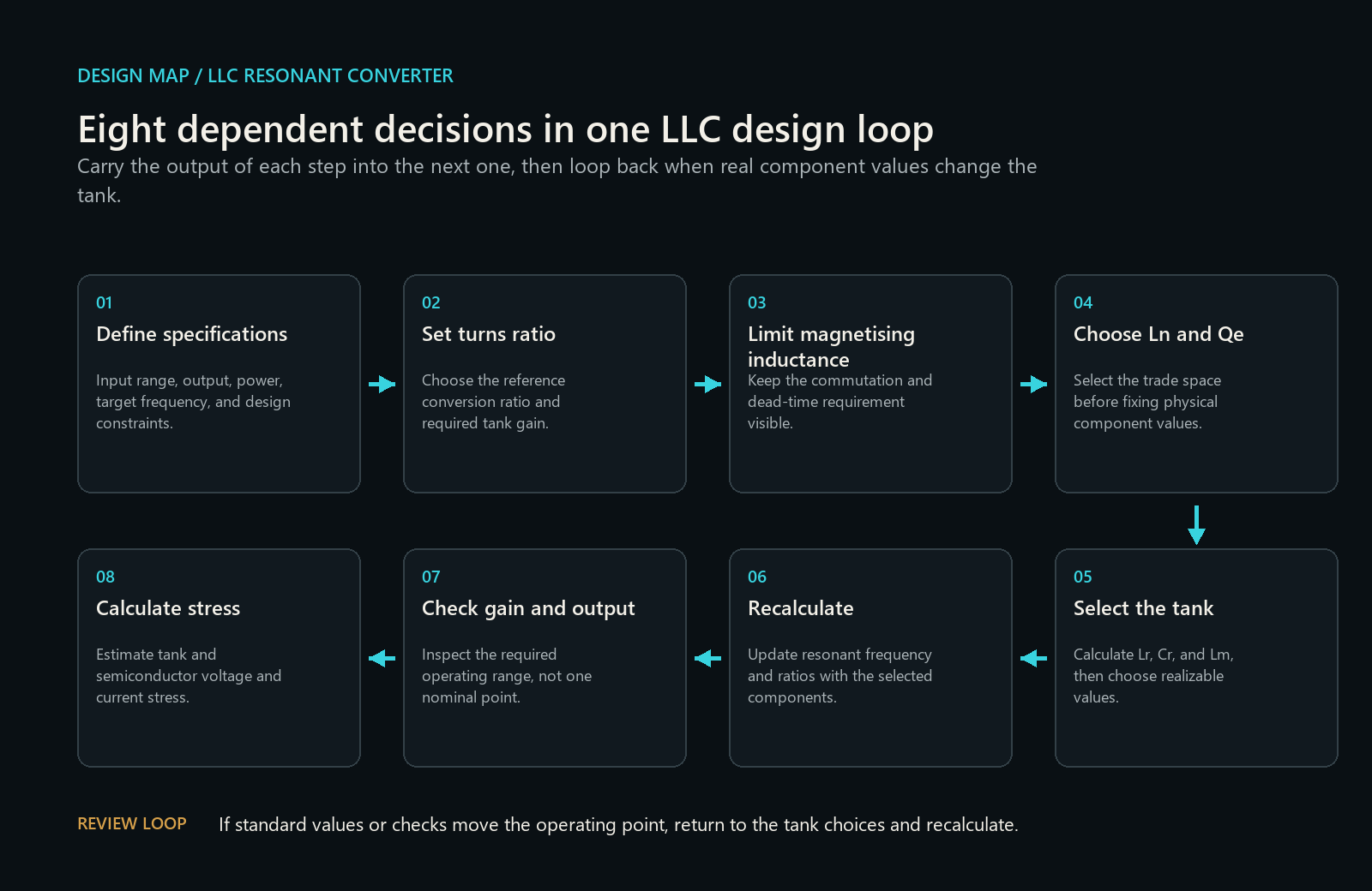
The published EEPower article contains the governing equations, worked numerical example, plots, and final design table. This page provides a practical decision map for using that sequence without losing the review logic between steps.
The eight design decisions
Before starting, keep four definitions beside the specification: the direction of the transformer turns ratio; the chosen definition of inductance ratio, commonly (L_n = L_m/L_r); the equivalent quality-factor convention; and the reflected-load and gain conventions. A correct equation with inconsistent definitions can still break the design chain.
1. Define converter specifications
Freeze the electrical problem before choosing the tank. At minimum, record input-voltage range, regulated output, maximum power, expected load range, target switching-frequency region, rectifier arrangement, efficiency assumption, and any control or component constraints already known.
Carry forward: one versioned specification table with units and named minimum, nominal, and maximum conditions.
Review before continuing: make sure each later gain and stress calculation can be traced to one of those stated operating conditions. Do not let a nominal value silently stand in for a range.
2. Calculate turns ratio
Choose the transformer ratio that establishes the reference conversion relationship between the primary bridge, transformer, secondary rectifier, and output. This ratio determines how much gain the resonant tank must provide across the input range.
Carry forward: turns-ratio convention, effective primary drive, reflected output quantity, and required tank gain at the relevant voltage extremes.
Review before continuing: write the ratio direction explicitly, such as primary-to-secondary. A reciprocal used in one equation can make the rest of the design look numerically reasonable while being physically wrong.
3. Determine max magnetizing inductance
The magnetising branch affects circulating current and the conditions available for commutation during dead time. Determine the maximum magnetising inductance allowed by the chosen soft-switching or commutation requirement under the stated assumptions.
Carry forward: the bound on magnetising inductance, the operating condition used to derive it, dead time, device capacitance assumption, and the margin policy.
Review before continuing: this analytical bound is a design constraint, not proof of zero-voltage switching in hardware. Device capacitance, parasitics, timing, temperature, and nonlinear magnetics still require stronger validation.
4. Select Ln and equivalent Q
Select the inductance ratio, commonly written as (L_n = L_m/L_r), and the equivalent quality factor used by the chosen design method. Together they shape the gain curve, frequency sensitivity, circulating current, and practical operating range.
Carry forward: selected (L_n), equivalent (Q), their definitions, the load-reflection convention, and the trade-off that justified the choice.
Review before continuing: inspect a region of the design plane rather than choosing one attractive point. A useful selection should leave room for tolerances, standard components, and operating variation.
5. Select tank values
Use the target resonant frequency, selected (L_n), equivalent (Q), reflected load, and the method's definitions to calculate (L_r), (C_r), and (L_m). Then choose realizable component values.
Carry forward: calculated and selected values side by side, units, tolerances, winding or leakage interpretation, and the intended implementation of each inductance.
Review before continuing: check whether the selected values can be built and measured. The resonant inductance may include transformer leakage by design, but that choice must match the model used in the equations.
6. Recalculate with final component values
Real values change the design. Recalculate resonant frequency, inductance ratio, characteristic impedance, equivalent quality factor, and any other derived quantity using the components that will actually be specified.
Carry forward: an updated parameter table generated only from the selected values.
Review before continuing: do not keep nominal derived quantities from step 5 after rounding components. This is the most important feedback point in the sequence.
7. Check gain, output, and tank response
Evaluate whether the updated tank can reach the required conversion ratio across the intended input and load range while remaining in an acceptable frequency and operating region. Plot the required gain and tank response so edge conditions remain visible.
Carry forward: the operating-frequency range, closest boundary cases, predicted output range, and any condition that approaches a gain or soft-switching limit.
Review before continuing: check the full required envelope, not only nominal input and full load. Treat an optimum at a search boundary as a warning that the design may not be comfortably contained.
8. Calculate current and voltage stress
Estimate resonant current, magnetising current, capacitor voltage, transformer stress, and semiconductor voltage and current at the relevant conditions. Use these results to inform component rating, loss, magnetic, thermal, and protection work.
Carry forward: worst analysed stress by operating condition, the model used, margin, and the higher-fidelity check still required.
Review before accepting: analytical stress is a screening result. Device nonlinearities, parasitics, tolerances, temperature, startup, transients, control behaviour, simulation, and prototype measurement remain separate evidence.
The evidence packet another reviewer should receive
The primary evidence for this work is the EEPower publication under Rafael Collado's byline, dated 6 April 2025. Its complete worked example is the governing source.
For project use, the eight-step calculation should leave a compact evidence packet:
| Record | Minimum content |
|---|---|
| Frozen specification | Values, ranges, units, topology, rectifier, and assumptions |
| Definition sheet | Turns-ratio direction, (L_n), (Q), reflected load, and gain convention |
| Calculated versus selected tank | (L_r), (C_r), (L_m), tolerances, and implementation notes |
| Recalculated parameters | Derived quantities from final selected values |
| Range plots | Required gain, achievable response, frequency limits, and boundary cases |
| Stress table | Condition, calculated stress, margin, and next validation method |
| Review record | Open assumptions, warnings, simulation evidence, measurements, and owner |
The publication establishes the public record, date, and authorship and documents the method. It does not independently validate the method, approve another converter specification, or prove a hardware implementation.
Turn each output into a review gate
At the end of each step, stop until the carry-forward record is complete. If step 6 changes the derived tank enough to weaken step 7 or step 8, return to the (L_n), (Q), or tank selection instead of patching the result with a wider frequency range.
The record is ready for engineering review when another reviewer can reconstruct the specification, definitions, selected values, range checks, stress assumptions, and remaining validation work without relying on undocumented spreadsheet state. Readiness for the next project phase still depends on the project-specific validation gates.
Boundary. This guide is an analytical design sequence. Final component selection still requires project-specific magnetics, semiconductor, thermal, control, safety, simulation, tolerance, and hardware validation.
Continue with Field Note 001 to inspect how one bounded LLC workflow records scope, gate outcomes, failures, and review state. Its Quickstart teaches traceability; it does not design or approve a converter.